


A very well written and informative article. I wish more people understood some of the difficulties that arise when High Speed Machining is mentioned, its not just go faster.
Latest Posts
Tools to Succeed in High-Speed Machining
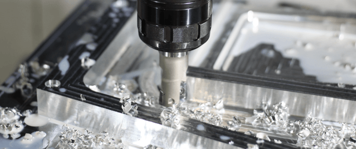
It probably doesn’t take much to convince you that machining at higher speeds can save you time and money. But like driving down the highway in your car, increasing your speed means that you are also increasing the inherent risk in the situation.
A tool holder rotating at 35,000 r.p.m. poses more of a danger than the same tool holder rotating at 8,000 r.p.m., just based on the kinetic energy involved. If a high-speed operation goes awry, you won’t have much time to act, and typically it’s your part, workholding or machine itself that bears the brunt of the damage, not to mention potential danger to the operator. Greater cutting speeds also mean greater heat and chip generation.
Nevertheless, with great risk comes great reward, and those who master machining at high speeds quickly reap the benefits of increased productivity. If necessity demands that you run at higher speeds, you need to choose the proper tooling and cutting strategies to reflect this or you may be doomed before the race even begins.
Nowadays when machinists talk about high-speed machining, they are usually discussing optimizing toolpaths and feeding strategies through CAM. You will hear phrases such as tool engagement, stepover and trochoidal milling.
A big revelation that many machinists have at some point in their career is that once you reach a certain cutting speed, the cutting temperature decreases. It may be counterintuitive, but in addition to decreasing cycle times, you are also increasing the life of the tool because heat dissipation is improved.
Whatever feeding strategy you utilize, they all serve the same purpose: maximizing your material removal rate with the equipment you have.
Fortunately, HSM toolpaths are usually a built-in feature to CAM software, so not much programming effort needs to go into this. Decades of research and countless papers are dedicated to this topic alone (and for good reason), however it’s still only one piece of the puzzle.
To maximize your speed potential, a holistic approach that considers tool, holder, machine and operator is essential.
Spindle speed and balance
The first step, as common sense as it may be, is knowing the maximum speed of your spindle. This will be your absolute ceiling when it comes to speed.
The next natural inclination is to look at your cutting tool. This means trading in your high-speed steel tools for carbide, or your carbide for super hard materials like PCD or CBN. Increasingly hard cutting tools largely translate to increasingly fast cutting speeds and today’s modern cutting geometry designs have made possible previously unthinkable speeds.
But many ignore the interface between the two: the tool holder.
Machining speed, besides depending on the physical limitations of the machine tool and cutting tool, will largely be governed on how well balanced the tool holder is. Balance is usually the focus when you’re talking about high-speed tool holders because it offers the greatest opportunity for improvement, but keep in mind that your maximum speed will only be as fast as the “weakest link” allows. If you have a 12,000 r.p.m. spindle, inserts that allow you to cut at 9,000 r.p.m., but your tool holder is only balanced for 8,000 r.p.m., then 8,000 is your max r.p.m.
The definition of high speed is different depending on who you ask, especially considering how fast cutting tool technology is evolving. Regardless, all these concepts apply whether you’re trying to get up to 10,000 r.p.m. or up to 30,000 r.p.m. But the importance of these concepts is amplified more and more as the speed increases.
The faster you spin, the more exaggerated any mass irregularities become and any speed harmonics present in the system will become increasingly excited. This translates into vibrations which, in turn, cause poor runout, surface finish, and ultimately wasted money spent on scrapped parts and equipment damage. Symmetry is your best friend at high speeds.
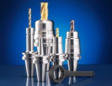
Shrink fit holders, hydraulic chucks, and high-performance collet chucks are typically the best examples of well-balanced tool holders because, by design, they’re symmetrical. They’re also generally slim – most of the mass is concentrated near their centerline.
And since we’re on the topic, it may be time to ditch the trusty sidelock endmill holders you’re used to. Mechanical milling chucks improve on endmill holders in every capacity (except for perhaps axial tool pullout), so they are the preferred alternative. This includes better balance. In fact, our MEGA Double Power chuck is a mechanical chuck that has been specifically designed for higher speeds.
This chuck, along with all other MEGA chucks we offer, have had all surfaces ground to a mirror finish. At high enough speeds, even slight anomalies in body concentricity come into play. Grinding all surfaces ensures that this factor is removed from the equation. They also make use of a notch-less nut, giving a perfectly cylindrical surface on the exterior, as opposed to the hexagonal or notched nut that you may commonly see.
Balancing act
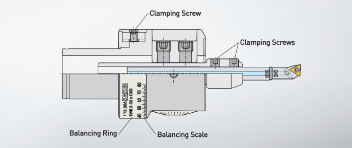
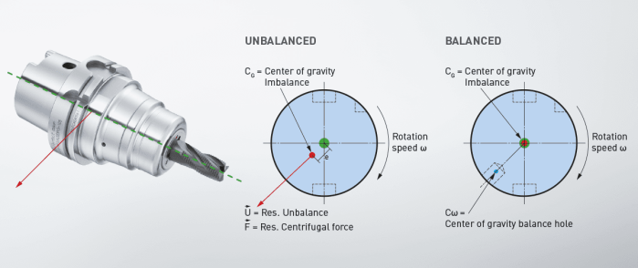
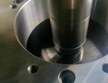
When it comes to fine boring tools, balancing can be a very serious issue. Single-point finish boring heads are fundamentally unbalanced because of their asymmetry and special care is required to ensure that they perform as expected. To say that bores are tolerance-sensitive features is an understatement, and this unbalance can easily scrap a part if you aren’t careful.
Running a boring head as fast as it can go should always be the goal, but progressively worse, unbalance can be introduced to the system as an unwanted byproduct. An unbalanced boring head can be very deceptive, because it will frequently bore your diameter within spec. Yet, upon further inspection, you will find that you have created an oval-shaped bore rather than a circle-shaped one.
Circularity/cylindricity is a common GD&T (geometric dimensioning and tolerancing) callout for shafts and holes, so boring head balance is crucial especially for those situations. At the very least, standard boring heads are usually pre-balanced for a diameter somewhat near the middle of their diameter range. If it’s a rigid, reasonably short bore, this will suffice.
When higher speeds and longer boring bars are needed, we offer a family of auto-balancing heads, designated EWB. These heads are well-balanced throughout their diameter range, because of a clever counterweight design inside the head that automatically adjusts a counterweight as you adjust the diameter.
Taper considerations
Equally as important as the tool holder body is the taper. In most cases, you’re stuck with the machine spindle taper you already have. But, if you’re in the market for a new machine and feeling the need for speed, it may be time to consider something with an HSK spindle.
HSK was developed in the 1990s specifically to combat problems that conventional steep tapers encounter at high speeds. The spindle taper will expand more than the holder under high centrifugal force because of differences in stiffness, which causes the tool to “sink” in the Z-axis. HSK was innovative in that the drawbar fingers go inside of the thin-walled taper and expand outward to clamp. Unlike steep tapers, high speeds are encouraged because they aid the clamping mechanism and proper seating.
Moreover, all HSK holders have flange contact in addition to taper contact as part of the standard. This eliminates the dreaded sinking phenomenon. Past 35,000-40,000 r.p.m., an HSK spindle becomes one of your only remaining options.
You can also remedy this unwanted Z-axis movement by using BIG-PLUS tooling, which is the same flange contact principle applied to steep taper holders like CAT or BT. In addition to preventing Z-axis sink, you will see huge gains in rigidity, given that you have a BIG-PLUS spindle.
What most people don’t know is that many machine tool builders already include BIG-PLUS spindles as a default feature, so there’s a good chance you have one and don’t even know it. This may be easier than making the big leap to HSK.
A word of caution: be careful not to confuse BIG-PLUS with the dual contact claims that are running rampant throughout the market. Keep in mind that only licensed tool holder manufacturers have the tools and gages to make true BIG-PLUS holders. Anyone can claim to have dual contact tooling with practically no proof. BIG-PLUS is not an international standard, so to be safe, use tooling clearly marked with “BIG-PLUS Spindle System – License BIG Daishowa Seiki,” otherwise you can seriously damage your spindle. All BIG KAISER tooling comes with true BIG-PLUS, so for our customers, this is never an issue.

Eliminate the bottleneck
In some cases, you’ll find that your spindle is the part of the chain that’s holding you back. Fortunately, there also exist alternative, after-the-fact methods by which to increase the maximum speed of your spindle.
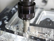
Spindle speeders, as their name suggests, are specialized holders that aim to do this. They really shine in applications that involve very small and monotonous work, and especially in larger spindles where you wouldn’t otherwise be able to ramp up the speed very high.
Basically, it’s possible to retrofit your conventional 40- or 50-taper machine into a high-speed micro machining center, without the cost of buying an entirely new machine. They’re available in a variety of different flavors, but the function remains the same: to significantly increase r.p.m. and cut down on time-consuming cycle times. Whether it’s electric, hydraulic, pneumatic, or spindle-driven, each version has its pros and cons.
Personally, we find that spindle-driven and pneumatic (air-driven) spindle speeders cover all of our bases. Spindle-driven speeders are really the only preferred option for situations in which you’re trying to increase your output up to ~20,000 r.p.m. (ours are designed with a planetary gear system that multiplies your input spindle speed by 4-6x). At the same time, you maintain high torque transmission since it’s mechanically driven, and you can still use relatively large diameter tooling.
In a perfect world, gear-driven systems would be used for all high-speed situations for this very reason. However, some applications call for speeds in excess of 100,000 r.p.m. (think of a dentist’s drill) and you can imagine that even the most impeccably oiled and designed gear system would start to melt well before that point.
This is where some other method of power transmission is required, like an air turbine. Air-driven spindle speeders provide the fastest speeds of any type by far and utilize ceramic bearings to withstand the high heat caused by internal friction. BIG DAISHOWA’s Air Power Spindle system, for instance, can reach speeds up to 120,000 r.p.m.
Exploring a new frontier
Once you start exploring this new frontier of speed, complications besides balance come into play. When someone uses a dial indicator to gage runout on a test bar, they are measuring what’s known as static runout. This gives you an idea of the level of dimensional precision involved in the manufacturing of the tool, holder and spindle assembly.
Let’s say you measure 5 tenths of runout with an indicator on a high-performance drill, which is within your tolerance range. If you run it at 3,000 r.p.m. or so, you wouldn’t really notice anything unusual in the generated hole that would dispute the earlier reading. However, you feel like you can run it faster.
At first you may feel satisfied with the shorter cycle times, but at a certain point after ramping up the spindle speed, you will gage the holes and realize that they’re suddenly oversized. Naturally, you go to measure the runout again and are dumbfounded when it still reads 5 tenths. You’ve just become the latest victim of dynamic tool runout.
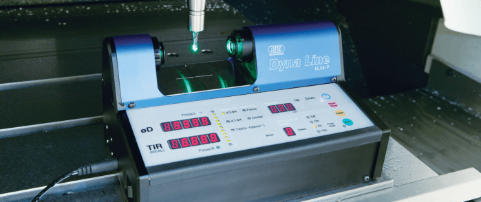
This type of runout is mainly caused by centrifugal forces associated with faster spindle speeds. These inertial forces will make the tool want to bend away from the centerline, so it will appear to fan outward at the tip when rotating. It’s hard to detect and even harder to accurately measure – it typically requires some sort of noncontact laser/light sensor device.
You wouldn’t encounter it under most standard application conditions because the forces require exceptionally fast speeds, but it can also be an issue with small diameter micro-machining tools that are easier to bend.
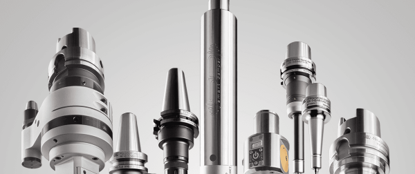
Ideally, you want to keep the mass of the tool holder as close to the centerline of rotation as possible. You also want to keep your tool as short as possible. This is the reason why there is general trend of higher max speed the smaller your tool holder is. You simply don’t have that much mass to throw around, so a higher speed can be attained safely. HSK-E style tool holders take this principle to the extreme.
In addition to having an HSK taper that’s already well-suited to higher speeds, this form of the standard aims to be as close to perfectly symmetrical as possible by the removal of all notches and drive key slots. These are commonly used in conjunction with very small diameter tools in order to reach ridiculously fast speeds. It’s not unheard of to achieve upwards of 50,000 r.p.m. in some applications. The only catch is, of course, you are using very small tools.
Again, when it comes to tool holders, the max speed largely depends on balance. Therefore, a high-speed machinist will be well-acquainted with the fickle art of balancing tool holders and the standards that are used. As tooling technology and speed progress, so too does the need for a proper standard by which to measure unbalance.
When good enough doesn’t cut it
As cuts get faster, tools get smaller, and tolerances get tighter, there is no longer any more room for the good-enough attitude. Traditionally, tool holder balance has always been measured based on the archaic ISO 1940-1 balancing standard (yes, we’re talking about the year 1940).
ISO 1940-1 is all-encompassing and applies to pretty much any type of rotating machinery, large or small. There’s nothing wrong with this old standard. In fact, it’s done an outstanding job up until this point. But the modern problem is twofold.
First, the standard is so generalized that it doesn’t account for many important variables unique to spindle/tool holder systems such as ATC repeatability, dynamic cutting forces and modular components.
Second, holders have gotten so small and are rotated so fast that, in some cases, achieving a balance benchmark like G2.5 is nearly impossible from a practical standpoint and oftentimes isn’t even necessary. Today’s balancing machines are realistically only sensitive enough to pick up on a minimum of around 0.5 g-mm.
In light of this issue, a new standard dubbed ISO 16084 has been developed. This standard considers (what seems like) every possible variable that influences balance in a tool holder/spindle system and was compiled by a joint team of industry experts and academics.
Like ISO 1940-1, the operator will only have to define a few variables to physically describe the holder and speed/balance requirements while the machine does the calculation work and spits out results in the familiar terms of gram millimeter (g-mm).
But unlike ISO 1940-1, this standard remains viable for any size tool holder or speed and only asks that you define whether or not you require standard balance quality or fine balance quality (rather than G6.3, G2.5, and so on).
You will find that the new standard is more lenient for small tool holder/high speed situations, to the point where the permissible unbalance is achievable. This leniency is even more apparent as you decrease speed and increase size. The reality is, we as an industry have been manufacturing all tool holders based on a strict standard that was never even designed with tool holders in mind.
Since ISO 1940-1 is usually the stricter standard, you may be asking yourself: what’s wrong with the old standard if it’s worked so far, or what’s wrong with a tool holder being more balanced than it probably needs to be?
A few things. Besides the fact that the math behind ISO 1940-1 breaks down and becomes impossible to achieve at smaller sizes and higher speeds, this also means that for years we have spent countless dollars and hours tricking ourselves into needlessly over-balancing tool holders in some cases.
Clearly, the transition to ISO 16084 will not happen overnight and it may not directly affect everyone but be on the lookout for it as it slowly gains headway.
Future impact
The tendency in machining has been toward faster and faster, and there’s no reason to believe that this trend will change anytime soon.
Developments in 3D printing technology, hybrid processes, and rapid digitalization and interconnectivity will greatly impact the manufacturing sector, no doubt. But that’s not to say that machining’s role will disappear, or even necessarily diminish.
Rather, there will be a continued shift toward high-speed machining to better complement and keep up with these processes. If you can make it faster, you can make it for cheaper. And if you can make it for cheaper, you have an edge over your competition.
Shops are in a constant race with each other, and those who don’t adapt easily to the constant advances in technology are left in the dust. With higher speeds becoming more of a necessity, proper understanding and implementation of these strategies is essential to survival.
Categories
Did you find this interesting or helpful? Let us know what you think by adding your comments or questions below.


Wes Daughaday
Wed, 01/05/2022 - 16:03