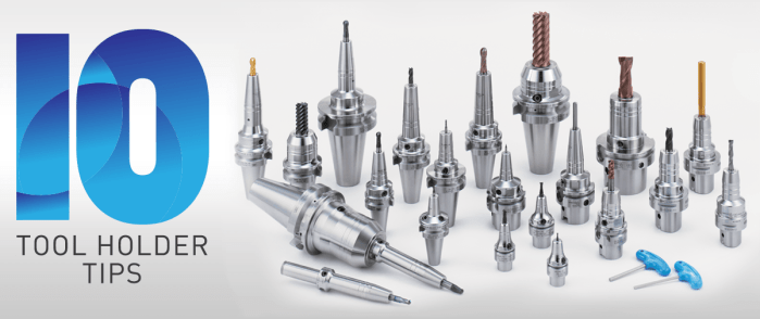
10 Tips for Improving Tool Holder Performance
The four critical requirements for tool holders are clamping force, concentricity, rigidity, and balance for high-spindle speeds. When these factors are dialed in just right, there’s nearly no chance of holder error and considerable cost reduction is achieved thanks to longer tool life and reduction of down-time due to tool changes.
Easier said than done, our experts shared some of their best, quick-hitting advice for top tool holder performance in different situations.
1. Balance holders as a complete assembly
Long-reach milling has some unique demands; when setting up this type of job, always balance tool holders as a complete assembly. While many tooling providers pre-balance their holders at the factory, it’s often inadequate, especially for long-reach applications.
2. Holder damage can go from bad to worse quickly
Wear and tear on holders can be costly in the end, but there are ways to protect against it. Inspect and care for your holders. Trauma on a holder or spindle—dings, scratches, gouges, etc.—can magnify quickly. One bad holder can spread its problems like an illness. If you’re seeing disruptions like these on your holders, get them out of the rotation.
3. The rule of thumb on holder dimensions
Looking for affordable ways to avoid vibration? Start by opting for a holder with a combination of the largest diameter and shortest length possible.
4. Rigidity can harm tapping operations
What many don’t realize about tapping operations is that a perceived strength of collet chucks—their rigidity—can actually be detrimental. Rigidity does very little to counteract the dramatic thrust loads imposed on the tap and part, exacerbating the already difficult challenge of weathering the stop/reverse and maintaining synchronization.
5. Balancing is crucial to five-axis machining
Five-axis machining introduces a whole new set of tooling challenges. While important in any type of machine, balance may be of most importance in full five-axis work. A well-balanced holder helps ensure the cutting edge of the end mill must be consistently engaged with the material in order to prevent chatter and poor surface finish quality.
6. Consider spindle speed requirements when choosing between shrink-fit and hydraulic holders
If you have to choose between shrink-fit and hydraulic holders in a long-reach application, consider the spindle speed required. If a hydraulic chuck exceeds its rated RPM, fluid is pulled away from the holder’s internal gripping gland, causing loss of clamping force. But when used within its recommended operating range, a hydraulic tool holder offers superior runout and repeatability. On average, a good shrink-fit holder has about 0.0003-inch runout, while a hydraulic chuck offers 0.0001 inch or better.
7. Don’t overlook the tool’s effect on holder performance
The cutting tool affects holding ability more than most machinists and engineers realize:
- Polished shanks reduce friction, as does the cleanliness.
- Oil and coolants reduce gripping power.
- Cutter shank roundness is often assumed to be close enough to perfect to ignore, but in reality, a 25 millionths tolerance is necessary for high-speed performance.
8. Not all dual-contact tooling is the same
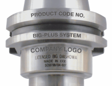
Anyone in the market for BIG-PLUS dual-contact tooling should consider this simple statement: Only a licensed supplier of BIG-PLUS has master gages that are traceable to the BIG grand master gages and have the dimensions and tolerances provided to make holders right. Everyone else is guessing and using a sample BIG-PLUS tool holder as their own master gage—a practice that any quality expert will advise against.
Look for the marking: “BIG-PLUS Spindle System-License BIG DAISHOWA SEIKI.”
9. You may have a BIG-PLUS spindle and not even know it
You’d be surprised how often we hear from our certified regrinders or engineers in the field about folks that didn’t realize their machine had a BIG-PLUS spindle—the message can get lost in the supply chain or during the sales process.
The easiest way to know if an interface is BIG-PLUS is to place a standard tool into the spindle and see how much of a gap there is between the tool holder flange face and spindle face. Without BIG-PLUS, the standard gap should be visible, or about 0.12 in. If it is BIG-PLUS, the gap is half of this amount, or only 0.06 in. These values change depending on 30 taper, 40 taper or 50 taper sizes, but the gap is visibly less than usual.
10. Use positive offsets during holder setup
It may be how it’s traditionally been done but touching off holder assemblies in each machine to establish negative tool offsets based on the zero-point surface—the vise, machine table, workpiece, etc.—is not the most efficient process. We think the choice is pretty clear: adapting machines to a single presetter so they can receive positive gage lengths is superior to using all types of machine-specific negative offsets.
This is a change to “the way things have always been done” that can be met with some resistance, but in the grand scheme of things, it’s a relatively small and simple step that makes life much easier. It’s a relatively low-cost opportunity to introduce more standardization of holder setup to the shop floor.
Holders are the bridge between the machine and the part. That’s a lot of pressure—literally and figuratively. It’s important to select, care for and use holders carefully from the day they are purchased until they’re tossed into the recycling bin.
From collet chucks to coolant inducers, BIG KAISER is North America’s source for standard-bearing tool holders that guarantees high performance. Explore the full lineup.


Did you find this interesting or helpful? Let us know what you think by adding your comments or questions below.