Rounding Up the Usual Suspects
When boring performance falls off, the cause may be any one or a combination of factors. These include workpiece stability, adequate stock allowance, tooling rigidity, insert grade and geometry and the matching of speeds and feeds to cutter capability. When experiencing overly long cycle times, short tool life or poor part quality, any or all of these factors should be reviewed. In any application, one factor may be more significant than others, but they also may be closely linked to each other. Changing one may mean another also has to be changed to get the desired results. However, when making test cuts, never change more than one thing at a time.
Part stability
Although the machining center and fixtures usually are not the first factors shops may consider, these can seriously impact tool performance if the part is not stable when being machined.
Once workholding rigidity is established, machine size and power influence cutting parameters. Although the same roughing head can be put on a CAT 50, CAT 40 and BT 30 taper, each will not be able to take the same cut. The same holds true for the depth of bore. A three-inch bore, 10- to 12-in. deep will work on a CAT 50, and can be done on a CAT 40 with extensions, but anything smaller than a 40-taper machine will not support the application.
Worn machine spindles and unstable fixtures are usually factors that cannot be changed and must be worked around. Sometimes these factors can kill an application altogether, but usually changes in insert types or cutting parameters will provide a solution.
Stock allowance
Often, operators are unsure of how much stock to leave for boring applications. Users may be more familiar with the speeds/feeds and stock allowances needed in turning applications, which don’t always apply to boring.
This is especially true in rough boring applications where a twin cutter is used. It is not uncommon to see drills that are so close to the final size of a part that only 0.020- to 0.030-in. of stock is left on diameter, which isn’t enough material to engage both insert tips on a twin cutter. This leads to chatter and poor tool performance. Parts without enough stock allowance and an open tolerance — plus or minus ten thousandths on the diameter — will work best with a singlepoint tool, or a twin cutter with one of its insert holders removed.
On the other hand, parts that have cored holes may have too much material to remove if the cored hole is not in the correct position. Even though the core diameter is within typical rough-boring standards for stock allowance, the core shift can produce a situation where the twin cutting tool is taking more material on one side of the bore than the inserts can handle.
Tool assembly rigidity
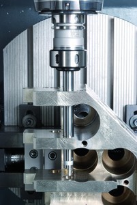
Often, boring tools are selected for an application based on a required bore diameter and gage length, without consideration for the actual boring depth and the extra reach required, if any. For example, an application may require 8 in. of reach through the part and/or fixture just to get to the bore, and only 2 in. of boring depth. This is quite different than an application that requires a boring depth of 10 in.
Modular tooling systems offer an infinite number of combinations for maximum rigidity and usage. In cases where tool length is needed, it is important to start with a larger base size and then reduce the tool diameter as necessary, rather than using the same bar diameter for the entire length of the tool.
Insert grade and geometry
Inserts are the critical contact point between a workpiece and tool. The most rigid boring assembly, complete with a balanced boring head, can perform miserably if the insert is not suited to the application.
Insert grade means little if the geometry does not provide a stable cut. Pressed geometry inserts usually have a less aggressive chipbreaker and hold up longer in stable conditions, but the radial depth of cut should be at least one-half of the insert nose radius. In applications that are critical due to factors such as deep or longreach bores, long-chipping materials, or part instability in the machine and/ or fixture, inserts with ground geometry will cut more freely.
Insert grades and coatings are continually being upgraded for specific applications. For steels, Cermet and triple-coated carbide grades are most common. Coated carbide grades are also used in cast iron applications, but stable conditions will also permit the use of silicon nitride and some cubic boron nitride (CBN) grades. Aluminum and other nonferrous materials can be run with uncoated carbide inserts, usually with highly positive ground chip breakers to prevent long strings of chips. For high-speed finishing of these materials, inserts with poly-crystalline diamond (PCD) tips or coatings also may be an option. Remember that a stable cut is the first requirement for long insert life.
Speeds & feeds When all other factors have been considered, it is time to determine the appropriate speeds and feeds for running the tools. These parameters are important to obtaining optimum freecutting conditions. Ideally, the boring bar is run at high speeds and more moderate feedrates; but again, this can be limited depending on the conditions previously cited.
A common mistake during rough boring is simply to multiply singlepoint feedrates by two when using a twin cutter. This usually is not an effective calculation; twin cutters can operate at feeds four times faster than those of finishing tools for the same diameter because a much larger nose radius can be used. For example, if finishing with a 0.008- or 0.016-in. nose radius, a 0.031-in. nose radius insert could be used for roughing. This doubles the size of the nose radius and using twin inserts doubles that to four.
Typically, roughing doesn’t require very fine, slow surface finishes so more rigid tools can be used at higher speeds. Feeding a twin cutter too slowly will lead to chatter without the right stock allowance. Rough cutters are designed for heavier cuts, requiring more material and harder feedrates.
When it comes to speeds, operators are sometimes hesitant to run proper surface footage when finishing. It’s important to optimize speed for insert life. If heavier cuts are being taken, running at a very high speed will create a lot of heat, reducing insert life. Lighter cuts don’t produce as much heat, so they can be run at higher surface feeds.


Did you find this interesting or helpful? Let us know what you think by adding your comments or questions below.