When is a Spindle Speeder Right for You?
Most machinists are familiar with the dilemma of having an otherwise capable, accurate machine on the shop floor that, unfortunately, is limited in terms of spindle RPM. When that inevitable job arises that requires higher RPM output, operators are left with the choice of replacing the machine altogether to gain higher productivity, or looking into an attachment, like a spindle speeder, to close the RPM gap.
There are a lot of different options in spindle speeders, using a lot of different technologies depending on how fast the spindle needs to go. Only a few decades ago, it was good enough to buy a spindle speeder that would increase an older horizontal boring mill from 2,000 RPM to maybe 12-15,000. That was usually an operation with a serpentine o-ring groove, usually a large part using a small end mill. With a 2,000 RPM spindle, that operation took forever. Mechanical spindle speeders were a natural outgrowth of this need - providing a way to take small tools onto bigger machines and make them more productive.
These days, new horizontal boring mills come standard with 6,000, 8,000, even 10,000 RPM spindles. So, to run a 1/8" end mill on an HSK 100 or BIG PLUS 50, the RPM gap is not as daunting as it once was. But modern spindle speeders take RPMs to yet another level, into the micro cutting space, where operators are running tools that only have 0.040" diameter, but are in-cut for as long as six hours at a time. This newer generation of spindle speeders in micro cutting is where the highest productivity gains are possible.
Doing the math
When moving into micro cutting, operators are faced with the option to buy a dedicated micro cutting machine, or adapt what is already in the shop. Knowing the material can go a long way, naturally, an operator can achieve different surface footages out of different workpiece materials.
An operator wants the highest possible spindle speed to achieve good chip separation, long tool life, good surface finish, and in the case of aluminum especially, avoidance of built-up edge (BUE). Below this threshold, operators are forced to use exotic or expensive cutting tool materials, like diamond, that possess a wide range of potential surface footages. Looking at hardened steels, there is a reasonably wide range of comfort. If an operator cannot achieve a minimum recommended surface footage however, tool life will be limited and surface finish will be compromised.
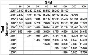
For a micro cutting setting particularly, if an operator has a tool diameter of 0.060" and runs at 300 SFM (an SFM value within hardened steel's range), it theoretically should be running at nearly 20,000 RPM.
For example, with a new machine tool with a spindle speed of 20,000 RPM, cutting tools are going to have to be bigger than 0.060" and used only for materials that run optimally at less than 300 SFM.
An operator or shop owner can crunch numbers to figure out where the potential machine would fit in terms of the range of tool diameters needed for a particular job. About 0.060" tends to be the tool diameter threshold; any smaller and a spindle speeder is likely to be a good choice.
What is available?
The smaller the taper size, the faster the spindle will be able to run. A typical 30-taper machine without a dual contact spindle interface will go as fast as 18,000 RPM. That will not include any additional engineering or special requirements. These machines are accounted for on standard taper spindles. With a dual contact system, as is the case with BIG-PLUS, you can nearly double these speeds, and a 30 taper will run as fast as 30,000 RPM. The graph displays the typical speed ranges.
A size 63 HSK (which is equal to the 40 taper) will yield about the same RPM as a BIG-PLUS dual contact system. But an HSK 63, cutting 300 SFM, is limited to tool diameters over 0.060". To shift to smaller tool diameters, smaller tool sizes are required. To use that tool size, an operator has to go down to an HSK 32, which has a spindle speed of 50,000 RPM. Conversely, that machine now cannot do any larger work.
An operator can also consider smaller HSK tool holders for high-speed and micro machining. The smaller taper sizes, 25 to 32, are designed for extremely small tools, but they also have to be balanced very precisely. A tool running at 50,000 RPM will weigh less than a third of a pound, but it has to balance to a G2.5 quality rating, which is a difficult process. Most operators consider the machine alone, but the tooling, when running at 50,000 RPM, takes a lot of precision and expertise in both manufacture and balancing to make it hit necessary quality ratings.
What problems develop when running a spindle at max RPM?
If you drive your car with the pedal on the floor, over time, heat will build up and the engine will blow. Similarly, in a machine running at or near maximum RPM, friction-caused thermal expansion will burn out bearings and gears. Even when paying careful attention to coolant, lubricant breakdown will happen, and the bearings will have to be replaced more often, meaning more downtime to service. It is not always in a machine's best interest to be running at or near maximum RPM. This is especially true for the extended time periods that micro cutting and small mold cutting machines and tools often require - 1, 2, 3 hours or more.
Another consideration is Z-axis deformation at the hands of thermal expansion. As it runs and heats up, the tool gets longer - so an operator has to compensate for that.
And finally, dynamic spindle stiffness - runout - is too frequently measured in the static state. An operator rotates the gauge bar roughly one dial indicator and arrives at an impressive runout number, perhaps 1 or 2 microns at 200 mm from the gauge line. But what happens to this number at 30,000 RPM? With a special tool holder, complete with a laser system to measure actual runout at speed, we see what that point is at maximum RPM. This value comparison is off of a machine rated for high-speed cutting at 30,000 RPM. The comparison clearly illustrates the difference between static and dynamic runout. At the cutting edge, at speed, we see an excess of 20 microns runout. Depending on the tool, that could be more than the diameter of the tool itself, which is not a good cutting condition.
Spindle speeder attachment solution
Instead of investing in a specialized machine, spindle attachments are another option that can achieve extremely fast RPM speeds. But there are five key requirements that high-speed spindle attachments must meet in order to maintain candidacy for micro cutting solutions. The tools must be ultra-high speed and be able to achieve acceptable dynamic runout. The spindles should be reasonably quiet, and exhibit low thermal distortion - the really fast spindles cannot grow due to the heat generated, a disadvantage for gear-driven spindle speeders.
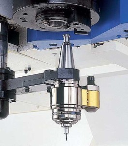
Perhaps most importantly, these spindle speeders need to be able to achieve Automated Tool Change (ATC), as operators do not want to have to stop production to hook up lines or activate the system due to tool change. With a BIG Kaiser spindle speeder, a single stopblock is attached to the spindle face. That stopblock engages a position pin on the tool itself, which serves two purposes. In the case of a gear drive system, it holds the tool steady while the spindle rotates. In the case of an air drive system, the air comes through the stop block, enters the position pin and into the turbine drive, finally exhausted out the side of the unit. BIG Kaiser is able to orient and align any of these so that the tool change is automatic, with no manual intervention.
Traditional gear drive systems, using planetary gear design, can get to 24,000 RPM. These types of spindle speeder systems could provide a big RPM jump for existing tools that are accurate and otherwise good, but max out at 5,000 to 8,000 RPM. Because it has gears running inside of it, however, it does exhibit Z-axis elongation which is unavoidable. Typically, this system will achieve stability at about the 20 minute mark of machining, so that is something to bear in mind when running with shorter cycle times. Another potential drawback is if the machine spindle is not in good condition to begin with, this spindle speeder will not correct for it. Instead, the amount of runout generated by the bad spindle will simply transfer into the good speeder, creating a lot of runout and a lot of stress on the bearings and gears inside. The accuracy requirement is <0.0002" TIR. Finally, operators need to account for the reduction in cutting torque; a speeder spindle is never as strong as the spindle itself.
An air drive system is a completely different concept than the gear-driven spindle speeder. In fact, the machine spindle does not rotate at all - the machine is merely moving the tool from one position to another. The drive is within the tool itself. The air enters into the stop block through the position pin, and into a turbine drive. The turbine drive then creates the torque and speed to the cutting tool. The bigger the turbine, and therefore, the spindle speeder unit size, the slower the potential speeds. Conversely, larger units are able to create more power. One detracting factor is if an operator does not have an M-Code built into the machine through the stop block to program the air pressure, then the regulator has to be manually changed. This is not a common scenario, however.
New air driven spindle speeders can go all the way to 120,000 RPM, but considerations have to be made for the extremely low torque in both of these spindles - neither can take on heavy cutting. With only half a horsepower at the cut, that translates to very light depths of cut and extended cutting time - fine cutting only. Greater torque is available with bigger tools and slower RPMs.
Collet considerations
When an operator is running the spindle at 80,000 RPM, the cutting tool has to be controlled, on center, to within one or two microns. A cutting tool with only 0.010" diameter taking a chip load of less than a tenth per tooth, must be managed to better than one tenth. That forces the tool to be extremely accurate, with all collets having been inspected and precise, the clamping nuts designed for high speed, the tool exhibits good balance and has achieved good clamping force.
Traditional ER systems are not accurate enough, nor are they capable enough, for high speed. This type of cutting requires a very specialized clamping system.
Speeder spindle in action
In order to illustrate a speeder spindles' micro cutting capabilities, product developers went so far as to cut a map of Japan onto a 0.75" by 0.75" block of 4140 pre-hardened steel (Rc40). A BIG Daishowa RBX7 air spindle, at 80,000 RPM, was used to generate speed. The test used a full-radius carbide ball nose end mill, with a feed of 16"/minute on the portions representing the ocean, and 2"/minute on the map of the Japanese landmass. Total cutting length was about 130" in total, with a two-hour cycle time and little tool wear.
That test was compared with a very good, but traditional machining center with a 20,000 RPM spindle, a job that took 7.5 hours, and the tool wear exhibited was extensive.


Did you find this interesting or helpful? Let us know what you think by adding your comments or questions below.