Enhancing Productivity Using Micro Cutting Tools
Manufacturing miniature parts and features is not new. In the past, EDM and laser technologies were used to create these features. Although these technologies worked for low volume jobs, they are not practical for the high volume micro applications that are in demand today.
High volume manufacturing of micro parts is driving a micro manufacturing revolution. The variety of applications is impressive: medical/dental components, micro molds, fluidic circuits, micro-valves, miniature actuators and motors – the list goes on. The micro mold industry, for instance, is expanding rapidly in North America, driven by developments in the medical, telecom fiber optic, automotive and micro drive industries.
In this article, we will explore what guidelines you should use when searching for ways to enhance productivity using micro cutting tools.
Basic geometry
Typically, we consider micro tools to be those with diameters smaller than 3 mm. However, it’s important to note that micro tools are not just shrunken versions of macro tools. There are many features of a macro tool – a ¾ in. tool, for example – that simply cannot be shrunk down to the micro size. It is important to understand the limitations of micro tools strictly due to their geometries.
For instance, micro tools must have ample web thickness to support the cutting action. As an example, Sphinx manufactures a deep hole micro drill that is less than 1 mm in diameter and runs 80 x D. This drill is only fluted at the tip because pecking in 10 x D increments is required, therefore it is beneficial to leave the remainder of the drill cylindrical for added strength.
What is considered very sharp for a macro tool – say 10 microns – is not for a micro tool. A 10 micron cutting edge radii taking a 3 micron chipload is not just dull, it is considered a highly negative rake.
The use of a coating on a micro tool decreases the performance by taking up too much flute space – using a coating, you will fill up the flutes, leaving you with a solid piece of shank to drill with. This is because the change in diameter due to the coating is too high of a percentage of the drill’s diameter below 0.2 mm.
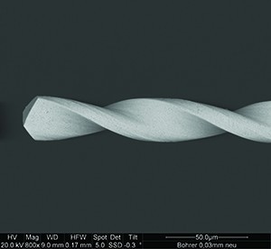
In the image presented here (figure 1), notice the ample web thickness for chip evacuation. The finely ground flutes still exhibit many features of a standard macro drill. No coolant is used in the deployment of the drill – such use weakens the overall structure of the tool. This 0.03 mm diameter drill is currently the smallest diameter that Sphinx manufactures as a standard item.
When micro milling, it is crucial that the feed per tooth equals the cutting edge radius. This is one of the more commonly overlooked parameters when micro milling.
There is also a limit to how small a tool’s cutting edge radius can be made. For instance, the cutting edge radius of a 0.05 mm cutter is not proportional to that of a ¾ in. cutter, because it simply is not possible to manufacture a proportionally small radius. Because of the relatively dull cutting edge radius, the amount of energy required for micro cutters relative to the MMR can by 2-10 times higher than conventional calculations used for macro cutters.
It is also crucial to use the shortest micro tool allowable for a job because the added tool pressure created by the dull cutting edge will cause deflection. A short tool will help resist deflection.
Run out concerns
Commonly in macro machining, end users often try to overcome their machines’ low spindle speed by applying a tool with three flutes or more. This enables you to achieve the appropriate feed rate. But it does not leave sufficient room for chip evacuation in micro machining applications – the chip is the enemy of small tools.
There are a number of considerations to be made when trying to manage run out at high speeds. The first step is to determine the appropriate chip load – as close to the tool’s cutting edge radius as possible. Once this has been attained, the only way to decrease cycle time is to increase the speed. Operating at higher cutting speeds will also enhance the surface finish of the finished feature by minimizing built up edge on the cutter.
Built up edge is a major concern when operating at low spindle speeds. It not only decreases tool life but also surface finish. In most cases, it will cause tool deflection, which leads to premature failure.
Built up edge is much more likely on a micro cutter. It leads to more force being required to remove the material, which results in cutter deflection, leading to premature failure. Because such a small amount of material is being cut, many times the cutting will involve more of a rubbing rather than cutting action, which increases the chance of built up edge.
Most modern machine tools are easily capable of running high speed steel micro cutters. But for those looking for a substantial increase in productivity, moving to carbide is required. Carbide requires much higher speeds than HSS, and not using higher speeds results in poor tool life.
Tool holders
CNC machines are being tasked with operating at more than 60,000 rpm to facilitate micromachining with small diameter cutting tools. These speeds bring balance and dynamic run out into play, both of which are difficult to manage when using large tool holders.
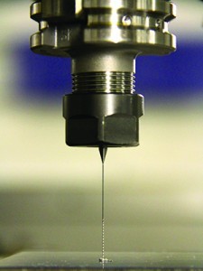
There are a few features of the holder pictured here (Figure 2) that are relevant for our discussion. For instance, it has a symmetrical design for high speeds; a ball bearing raceway for concentric collapse of the collet around the cutter; and precision ground threads.
You simply cannot rely on the tool’s tolerance alone to be within the tolerances required of your part. There are many other variables to consider, such as dynamic run out and balance.
Controlling run out
Controlling run out in micro applications is one of the easiest methods of increasing tool life and enhancing surface finish. The cutting edge experiencing the highest amount of run out will do the majority of the cutting. Therefore, nearly all of the tool pressure and tool wear will occur primarily on that one cutting edge. Because the cutting is done primarily with one cutting edge, the tool life will be substantially less than a tool rotating about the centerline.
If all cutting edges are not engaged in the material, the feed per tooth will be much higher than expected because the calculations assume all cutting edges are cutting, not one. With a micro tool with three flutes, for example, if you program a specific feed per tooth based on calculations, and only one cutting edge engages due to excessive run out, the cutter will fail prematurely due to the high load placed on the one cutting edge.
Using a higher quality collet and tool holder can increase tool life and save money. In a recent example of this I was involved with, a customer achieved 2-3 times the previous tool life by making such a switch.
The hurdle we typically face is the cost of the higher accuracy collet. But the savings are real. For instance, in one application drilling into a steel workpiece, 0.590 in. deep using a 0.118 in. diameter carbide drill, 2,300 holes were made using a drill in a tool holder with 0.00008 in. run out accuracy. Only 800 holes were drilled using a tool holder that had 0.0006 in. run out accuracy. In this example alone a shop could save as much as $280 each month with such an investment.
Balance
Balance is independent of speed – it is constant at any speed. The resultant force created by an imbalance exponentially increases with speed. Therefore, the amount of imbalance will not change as spindle speed increases.
However, the force created by the imbalance will increase exponentially with speed. Because micro tools require higher speeds, effective forces created by imbalance will be much more apparent.
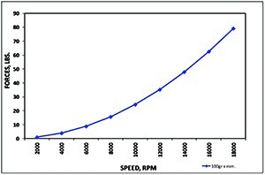
In the chart displayed we show the exponential resultant force curve created by a constant imbalance of 100 gram millimeters and increasing spindle speeds. Logically, large cutters can withstand larger forces applied to them. But unfortunately the tools operating at the highest speeds, encountering the highest resultant forces, are the smallest and weakest diameters. It is crucial that we control these forces using well-balanced, high accuracy tool holders.
Essentially, there are four critical considerations in getting the most out of your micro tools:
- Ensure that the chip load equals the cutting edge radius;
- Ensure that you operate at the highest speed possible;
- Match your tool holder with the job at hand to ensure a high run out accuracy; and
- Ensure that your tools are well balanced.
Did you find this interesting or helpful? Let us know what you think by adding your comments or questions below.


Add new comment